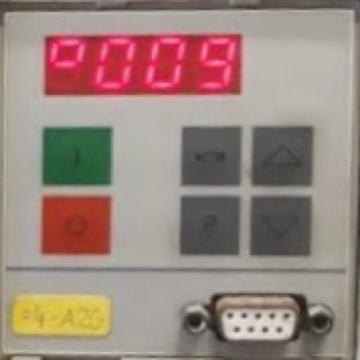
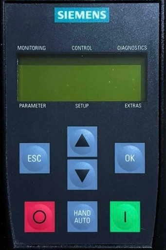
Masterdrive
F001
Main contactor checkback: If a main contactor checkback is configured, no checkback occurs within the time set in P600 after the power-up command. In the case of externally excited synchronous motors (P095 = 12), there is no checkback for the excitation current unit.
F002
Pre-charging: When pre-charging, the minimum DC link voltage (P071 Line Volts x 1.34) of 80 % has not been reached. The maximum pre-charging time of 3 seconds has been exceeded.
F006
DC link overvoltage: Shutdown has occurred due to excessive DC link voltage.
F008
DC link undervoltage: The lower limit value of 76 % of the DC link voltage (P071 Line Volts), or of 61 % when kinetic buffering has been enabled, has been fallen short of. Undervoltage in the DC link in ’normal’ operation (i.e. no SIMULATION). Undervoltage in the DC link with active kinetic buffering and speed less than 10 % of the rated motor speed. It was a ’brief power failure’ which was not detected until system recovery (auto restart flag).
F010
DC link overvoltage: Due to excessive DC link voltage, shutdown has taken place.
F011
Overcurrent: Overcurrent shutdown has occurred. The shutdown threshold has been exceeded.
F012
I too low: During excitation of the induction motor, the current did not rise above 12.5 % of the setpoint magnetizing current for no-load operation.
F014
I too low: During excitation of the motor, the current component is less than 25 % of the motor no- load current.
F015
Motor stall: Motor has stalled or is locked.
F017
SAFE STOP: SAFE STOP operating or failure of the 24 V power supply during operation.
F018
F set fly: The found set frequency could not be implemented.
F019
Motor not found: During flying restart without tachometer: Search in both directions of rotation not possible (one direction blocked) and motor has not been found.
F020
Motor temperature: The motor temperature limit value has been exceeded.
F021
Motor I2t: Parameterized limit value of the I2t monitoring for the motor has been exceeded.
F023
Inverter temperature: The limit value of the inverter temperature has been exceeded.
F025
UCE Ph. L1: UCE upper switch (Compact PLUS) / or UCE has tripped in phase L1.
F026
UCE Ph. L2: UCE lower switch (Compact PLUS) / or UCE has tripped in phase L2.
F027
UCE Ph. L3: Fault pulse resistor (Compact PLUS) / or UCE has tripped in phase L3
F028
Supply phase: The frequency and the amplitude of the DC link ripple indicate a single-phase power failure.
F029
Meas. value sensing: A fault has occurred in the measured value sensing system.
F035
Ext. Fault 1: Parameterizable external fault input 1 has been activated.
F036
Ext. Fault 2: Parameterizable external fault input 2 has been activated.
F037
Analog input: An analog input is taking place in operating mode 4..20mA and a wire break has occurred.
F038
Voltage OFF during parameter storage: During a parameter task, a voltage failure has occurred on the board.
F040
AS internal: Incorrect operating status
F041
EEPROM fault: A fault has occurred when storing the values in the EEPROM.
F042
Calculating time: Calculating time problems
F044
BICO manager fault: A fault has occurred during the softwiring of binectors and connectors.
F045
Opt. Board: A hardware fault has occurred when accessing an optional board.
F046
Par. Task: A fault has occurred during the transfer of parameters to the gating unit processor.
F047
Gating Calc Time: The calculating time in the gating unit computer is not sufficient.
F048
Gating Pulse Freq: The pulse frequency set in P340 is not permissible.
F049
SW version: The firmware versions on the CU have different firmware release.
F050
TSY Init.: Error when initializing the TSY board.
F051
Speed encoder: Digital tachometer or analog tachometer sensing are faulty.
F052
n-Cntr.Input: Control track input (-X103/27, or -X104/27 Compact PLUS) is not high: - Tachometer line broken - Tachometer fault The fault input on the TSY was activated.
F053
Tachometer dn/dt: The permissible change value of the speed encoder signal P215 dn(act,perm) has been doubly exceeded.
F054
Sensor board initialization fault: A fault has occurred during initialization of the encoder board.
F056
SIMOLINK telegram failure: Communication on the SIMOLINK ring is disturbed.
F057
Brake does not open: The brake has not opened, the output current of the converter has exceeded the parameterized current threshold (U840) for longer than one second (with the rotor locked)
F058
Parameter fault Parameter task: A fault has occurred during the processing of a parameter task.
F059
Parameter fault after factory setting/init.: A fault has occurred in the initialization phase during the calculation of a parameter.
F060
MLFB is missing: This is set if the MLFB = 0 after exiting INITIALIZATION (0.0 kW). MLFB = order number.
F061
Incorrect parameterization: A parameter entered during drive setting (e.g. P107 Mot Rtd Freq, P108 Mot Rtd Speed, Incorrect P340 Pulse Frequency) is not in a permissible parameterization range (depending on control type)
F062
Multi-parallel circuit not Compact PLUS: Fault in connection with the multi-parallel circuit or board ImP1 has been detected.
F065
Scom Telegram: No telegram was received at an Scom interface (Scom/USS protocol) within the telegram failure time.
F070
SCB initialization fault not Compact PLUS: A fault has occurred during initialization of the SCB board.
F072
EB initialization fault: A fault has occurred during initialization of the EB board.
F073
AnInp1SL1: 4 mA at analog input 1, slave 1 fallen short of
F074
AnInp2 SL1: 4 mA at analog input 2, slave 1 fallen short of
F075
AnInp3 SL1: 4 mA at analog input 3, slave 1 fallen short of
F076
AnInp1 SL2: 4 mA at analog input 1, slave 2 fallen short of
F077
AnInp2 SL2: 4 mA at analog input 2, slave 2 fallen short of
F078
AnInp3 SL2: 4 mA at analog input 3, slave 2 fallen short of
F079
SCB telegram failure: No telegram has been received by the SCB (USS, peer-to-peer, SCI) within the telegram failure time.
F080
TB/CB initialization fault: Fault during initialization of the board at the DPR interface
F081
OptBrdHeartbeat-Counter: Heartbeat-counter of the optional board is no longer being processed
F082
TB/CB telegram failure: No new process data have been received by the TB or the CB within the telegram failure time
F085
Add. CB initialization fault: A fault has occurred during initialization of the CB board.
F087
SIMOLINK initialization fault: A fault has occurred during initialization of the SLB board.
F090
Mld Param.: An error occurred when attempting to change a parameter from the standstill measurement or the rotating measurement (Mot ID).
F091
Mld Time: The rotating measurement takes longer than programmed in a measured status. Possible causes: Load torque too high Load torque not uniform Ramp-function generator disabled
F095
Mld n(set): Due to entries for - Permissible phase sequence - Maximum frequency, - Minimum speed, - Changeover frequency between V and I model, - Start of field-weakening frequency, - Frequency suppression bandwidth it was not possible to determine a permissible frequency range for the rotating measurement.
F096
Mld abort: The rotating measurement was aborted due to the inadmissible external intervention.
F097
Mld meausred value: The measured values for the nominal ramp-up time when optimizing the controller deviate too greatly. Cause: very unsteady load torque
F098
Mld Tachof: The rotating measurement has detected a fault in the speed actual value signal. The fault value defines the type of fault. The fault measurement may have been erroneously generated if the drive speed is externally forced (e.g. completely locked drive generates the "no signal" message)
F100
GRND Init: During the ground fault test, a current not equal to zero has been measured, or an UCE or overcurrent monitoring has responded, although no value has yet been triggered.
F101
GRND UCE: During the ground fault test, the UCE monitoring has responded in a phase in which no valve has been triggered.
F102
GRND Phase: During the ground fault test, a current flows in a phase in which no valve has been triggered or the UCE monitoring has responded in the phase in which the valve has been triggered.
F103
Ground fault: There is a ground fault or a fault in the power section. During the ground fault test, a current flows from the phase in which a valve has been triggered, the overcurrent comparator has responded, or a UCE monitoring has responded in a phase in which a valve has been triggered.
F107
MLd = 0: A fault has occurred during the test pulse measurement
F108
Mld Unsym: During the DC measurement, the measurement results for the individual phases differ significantly. The fault value indicates which quantity(ies) is (are) concerned and in which phase the greatest deviation occurred.
F109
Mld R(L): The rotor resistance determined during DC measurement deviates too significantly from the value which was calculated by the automatic parameterization from the rated slip.
F110
Mld di/dt: During test pulse measurement, the current has increased significantly faster than was expected. Thus for the 1st test pulse, an overcurrent condition occurred within the first half of the minimum switch-on time
F111
Fault e_Func: A fault has occurred while calculating the equalization function.
F112
Unsym I_sigma: The individual leakage test results deviate too significantly.
F114
MId OFF: The converter has automatically stopped the automatic measurement due to the time limit up to power-up having been exceeded or due to an OFF command during the measurement, and has reset the function selection in P115.
F115
KF internal: A fault has occurred during calculations in the context of the MotID.
F116-F147
Technology board fault: See TB documentation
F148
Fault 1 Function blocks: An active signal is present at binector U061
F149
Fault 2 Function blocks: An active signal is present at binector U062
F150
Fault 3 Function blocks: An active signal is present at binector U063
F151
Fault 4 Function blocks: An active signal is present at binector U064
F152
Signs of life repeatedly invalid.: After an appropriate number of invalid signs of life, the sign of life monitoring block has gone into fault status.
F243
Link int.: Fault in internal linking. One of the two linked partners does not reply.
F244
ParaLink int.: Fault in the internal parameter linking.
F255
Fault in EEPROM: A fault has occurred in the EEPROM.
FF01
Time slot overflow: A time slot overflow which cannot be corrected has been detected in the higher-priority time slots.
FF03
Access fault Optional board: Serious faults have occurred while making access to external optional boards (CB, TB, SCB, TSY ..).
FF04
RAM: A fault has occurred during the test of the RAM.
FF05
EPROM fault: A fault has occurred during the test of the EPROM.
FF06
Stack overflow: Stack has overflowed
FF07
Stack underflow
FF08
Invalid processor command should be processed.
FF09
Invalid format in a protected processor command.
FF10
Word access on uneven address.
FF11
Jump command to uneven address.
FF13
Wrong firmware version: A version conflict between the firmware and the hardware has occurred.
FF14
FF processing: Unexpected fatal error (During processing of the fatal errors, a fault number has occurred which is unknown to date).
FF15
CSTACK_OVERFLOW: Stack overflow (C-Compiler Stack)
Siemens
